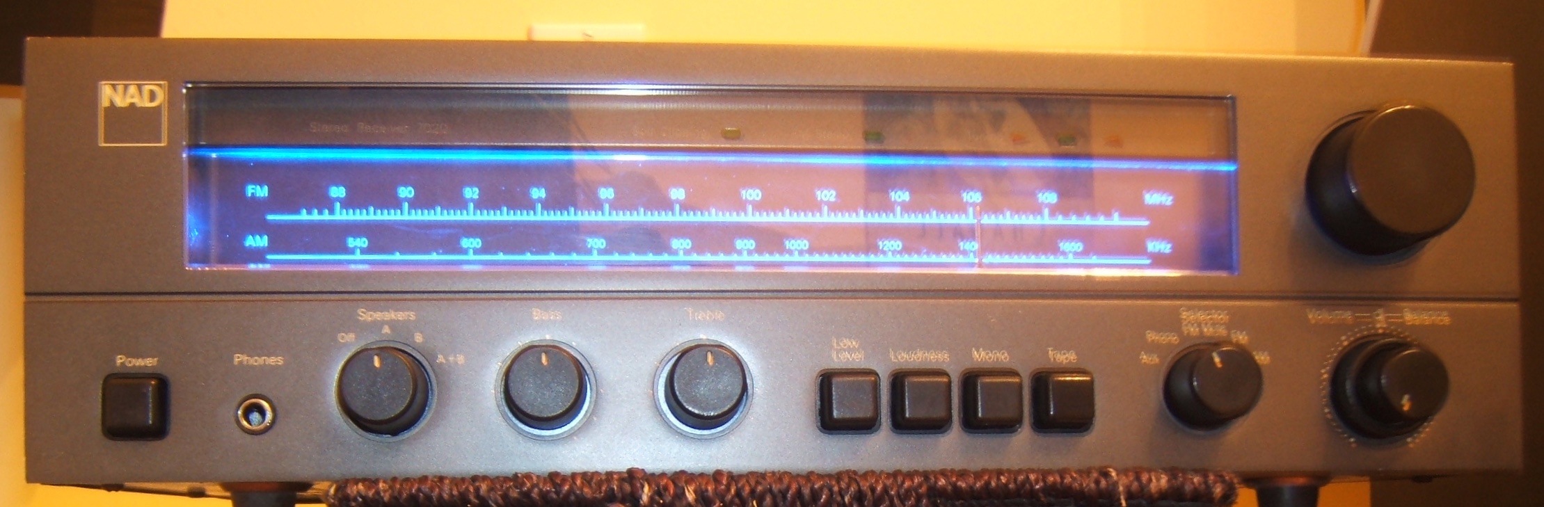

Anyone that grew up in the ’80s as a guitarist knows about the ADA MP-1 and how it was used by the top guitarists of that era. The ADA MP-1 is a classic rack mount tube preamp that features an all analog tube signal path. Its sound has a distinctive mid range and clear articulation. I had one of these in the late ’90s and regrettably sold it. A few years ago, I found one in bad condition, with the front panel mangled and its been sitting in a box ever since, waiting to be revived.
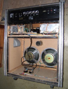
I didn’t take any pictures of the unit in its original state but the completed, repaired unit shows signs of the abuse it went through. The front panel was broken and it was quite noisy, as most of the MP-1s are.
This project was to be done in three steps:
- Repair the ADA MP-1 front panel
- Refurbish the electronics
- Bring the noise floor to a lower level (better “noise mod”)
The Front Panel
The control buttons on this unit were mostly broken: Some worked, some didn’t and some were intermittent. The contacts are a “momentary on” type so I proceeded to start removing the existing control appliqué and replace it with real push buttons. By tracing out the original connections, I could replicate them with hookup wire.
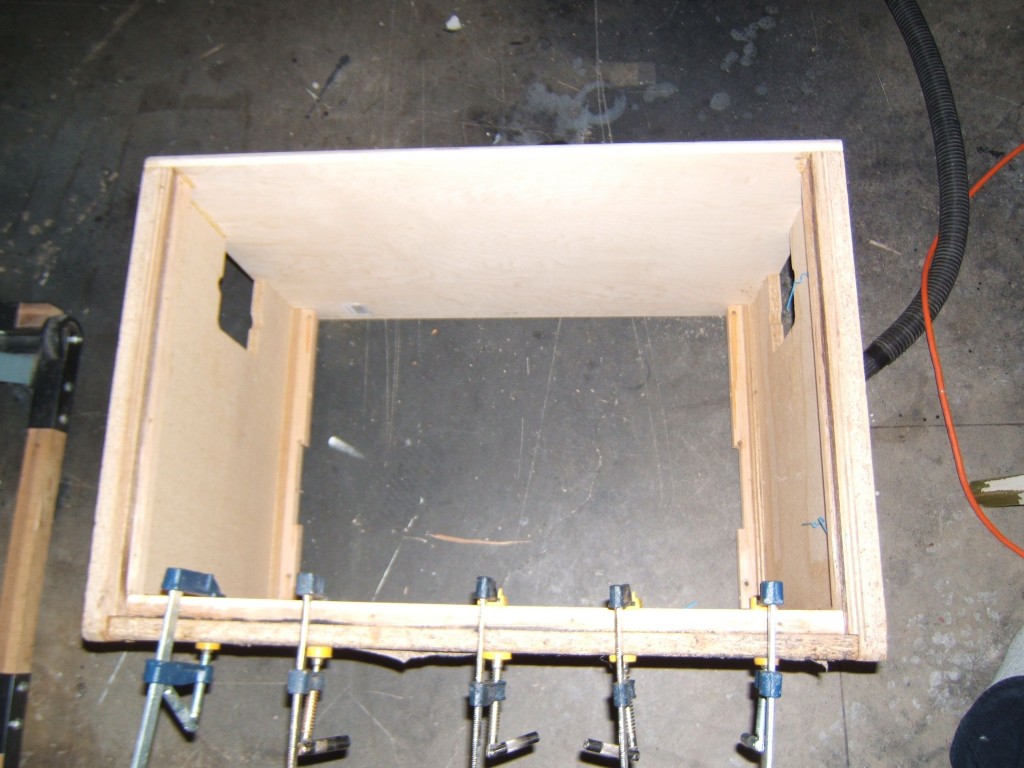
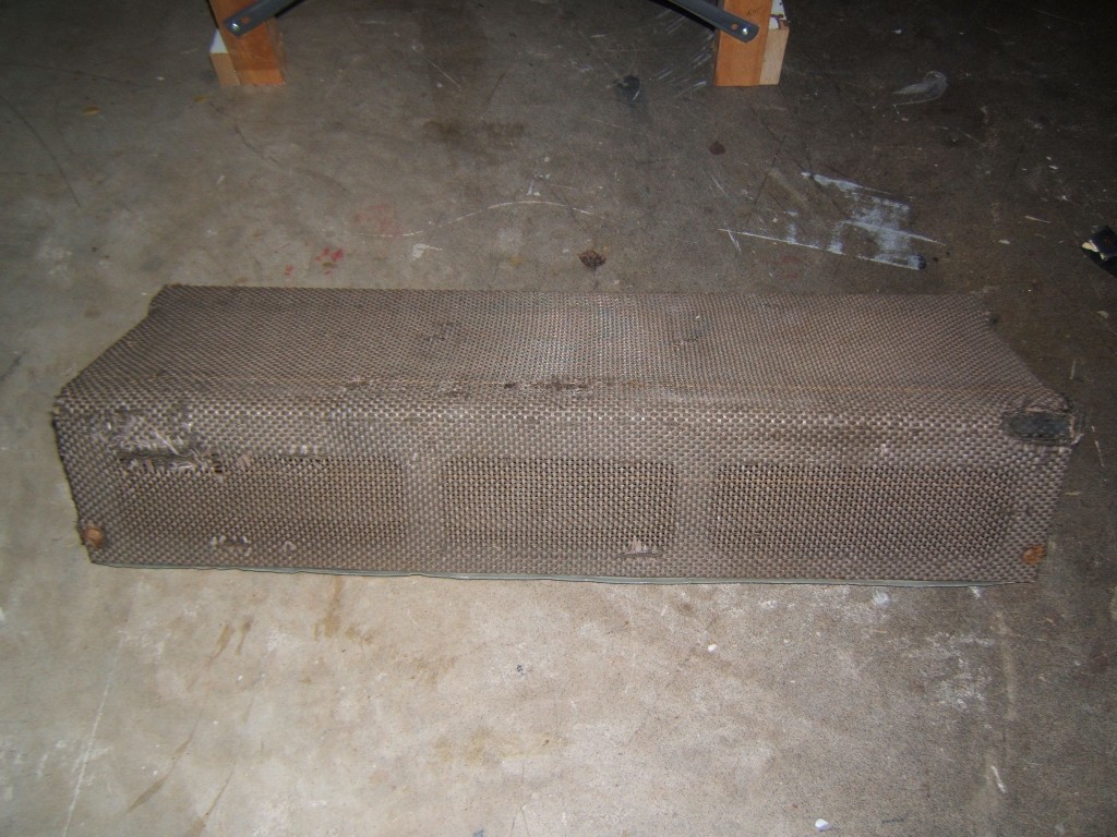
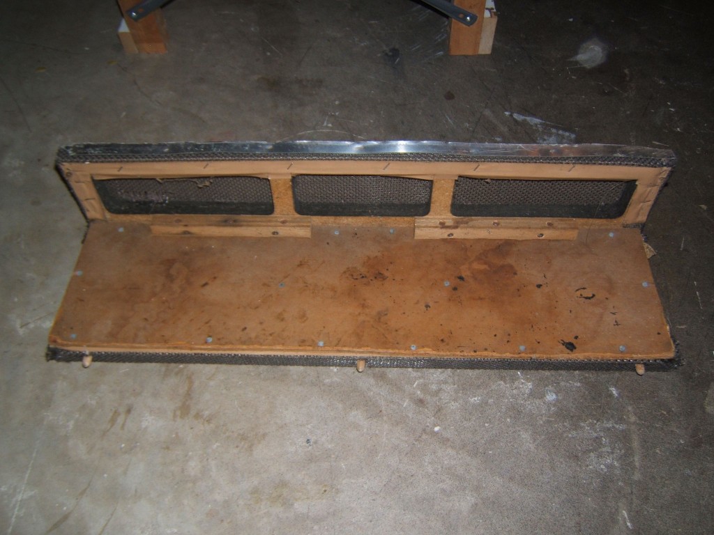
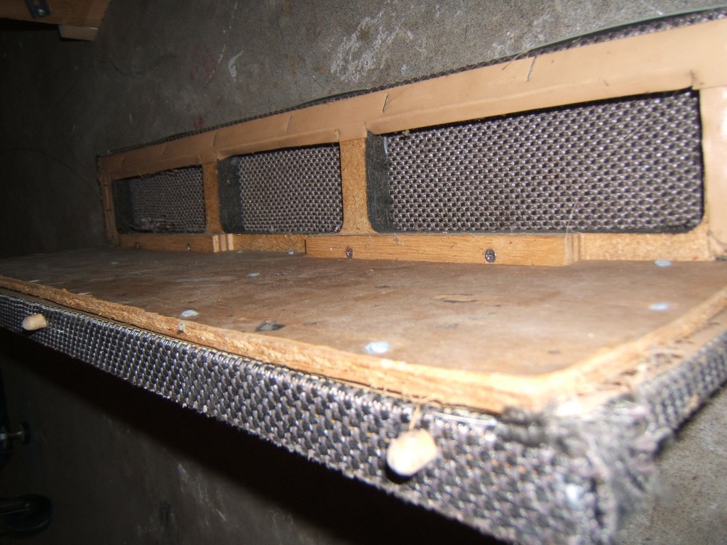
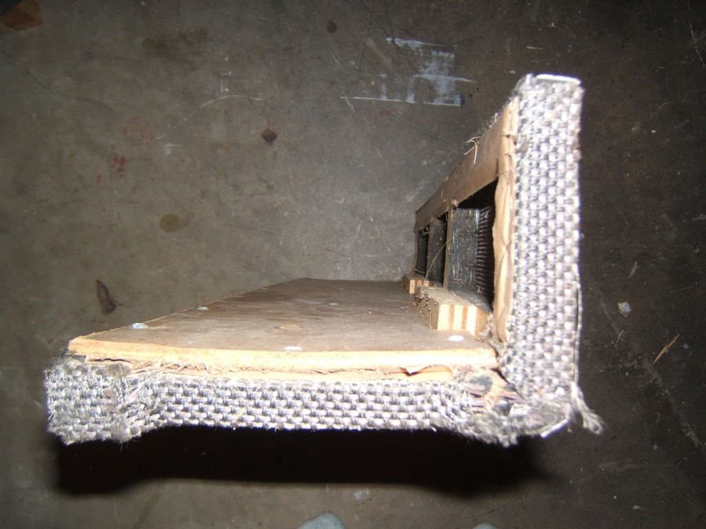
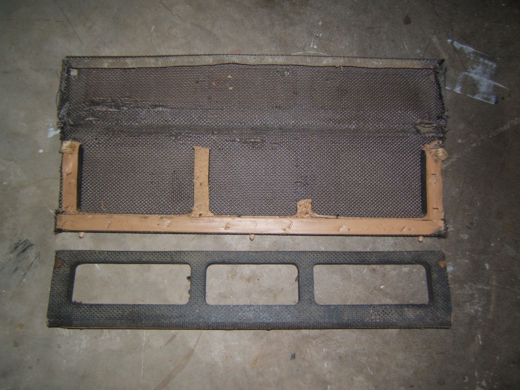
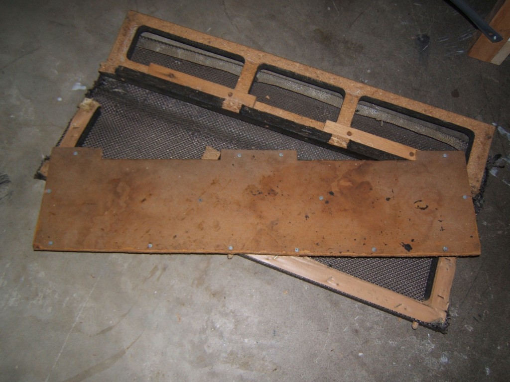
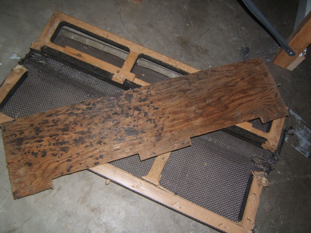
The original appliqué needs to be removed from the faceplate. You need to remove the front panel, then, with a hair dryer, heat up the flexible faceplate that is glued on the metal front panel. It should come off very easily. The faceplate is 3 parts:
- The coloured portion that has all the user indications on it.
- 1st side of the button connections
- 2nd side of the button connections
To trace the circuit, you need to undo the three parts of the flexible faceplate. Again, a little bit of heat is all that’s needed to take everything apart. Just pull slowly and you’ll be fine.
-
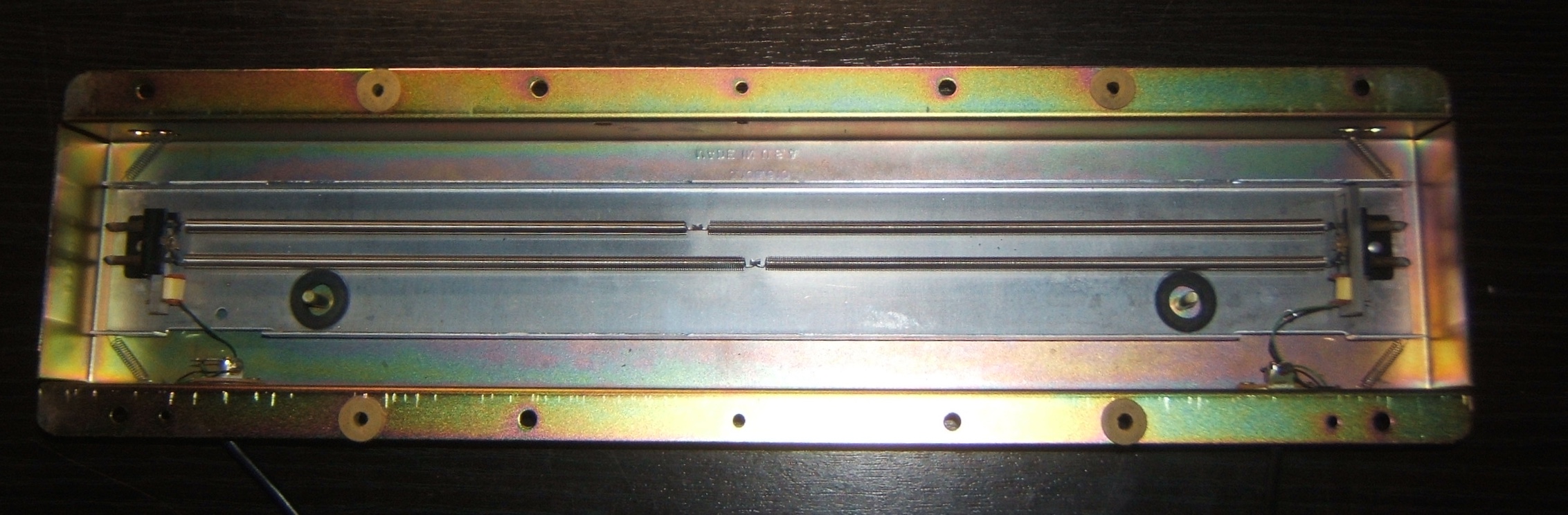
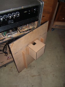
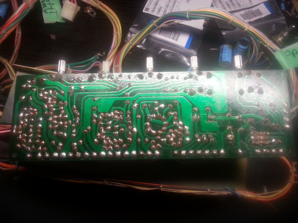
- ADA MP-1 Front Panel Removed
-
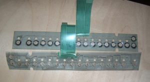
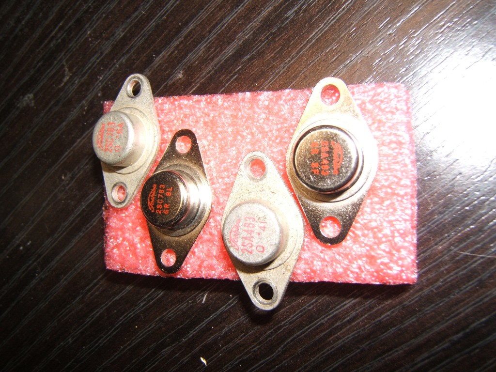
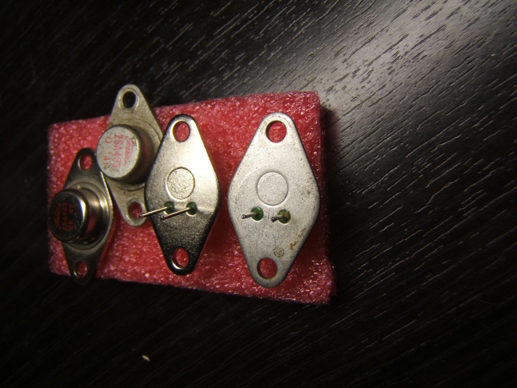
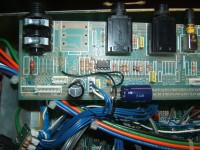
- ADA MP-1 panel buttons
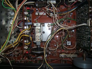
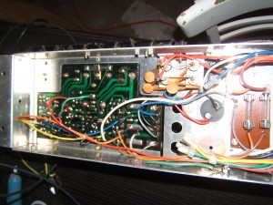
-
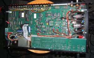
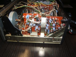
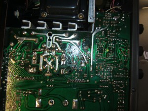
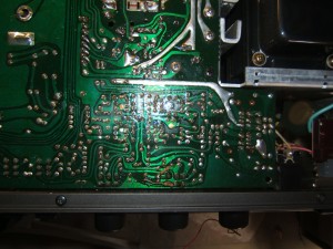
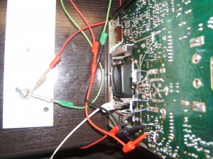
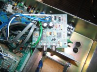
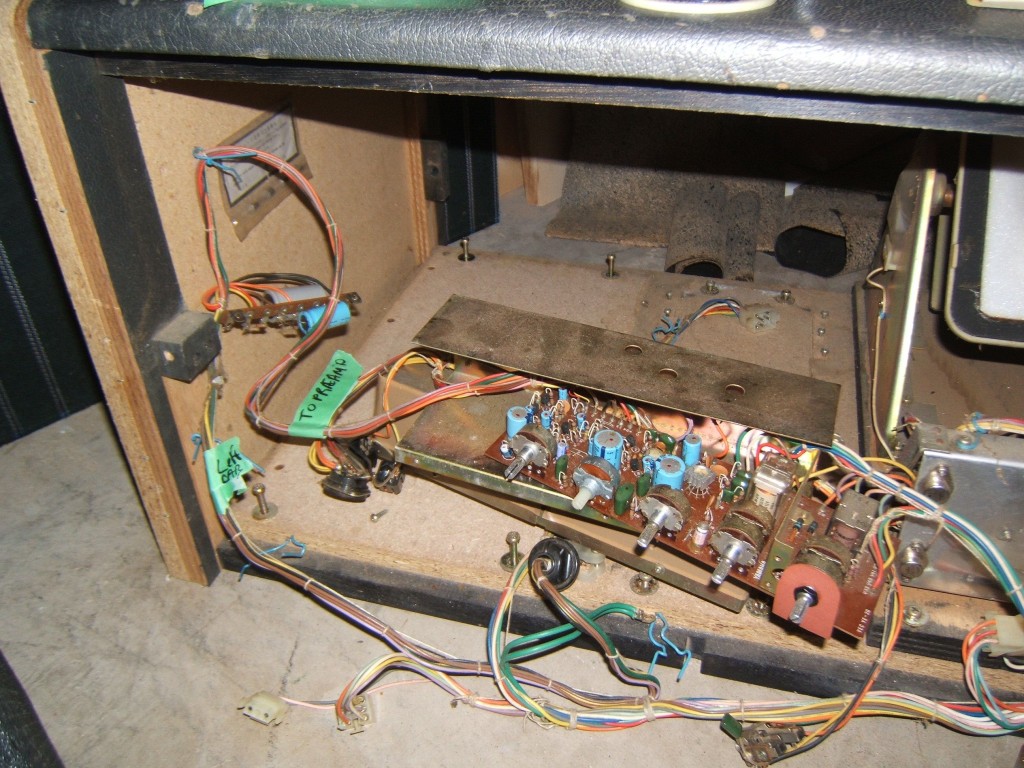
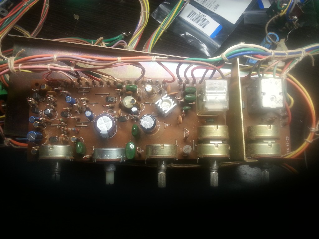
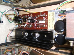
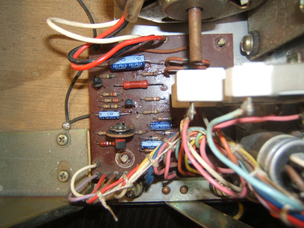
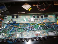
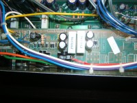
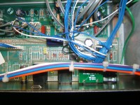
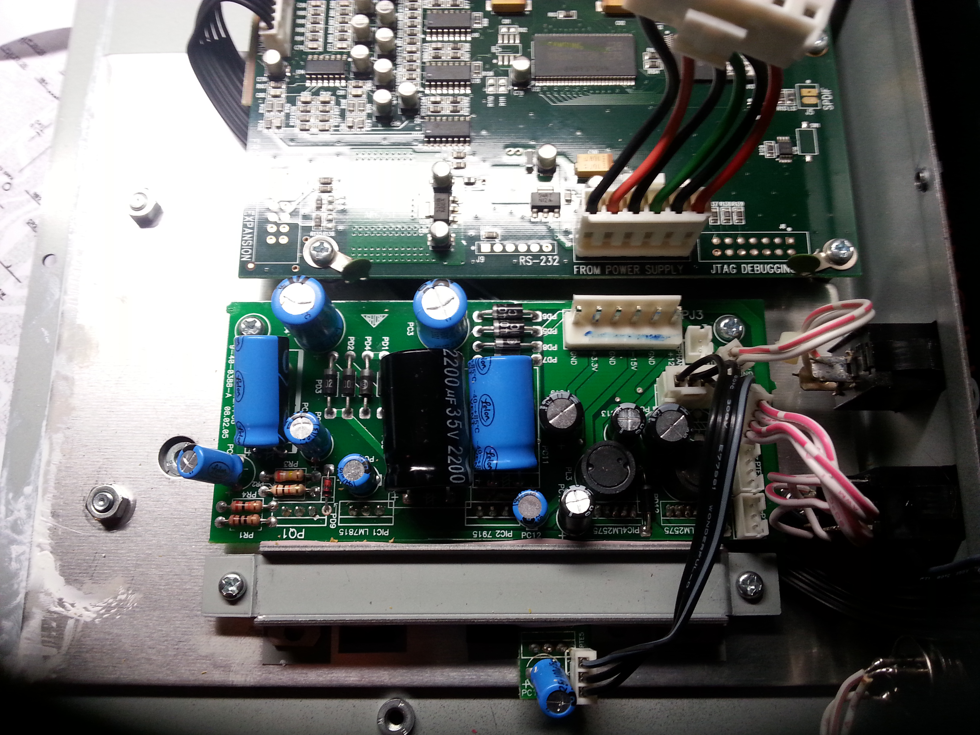
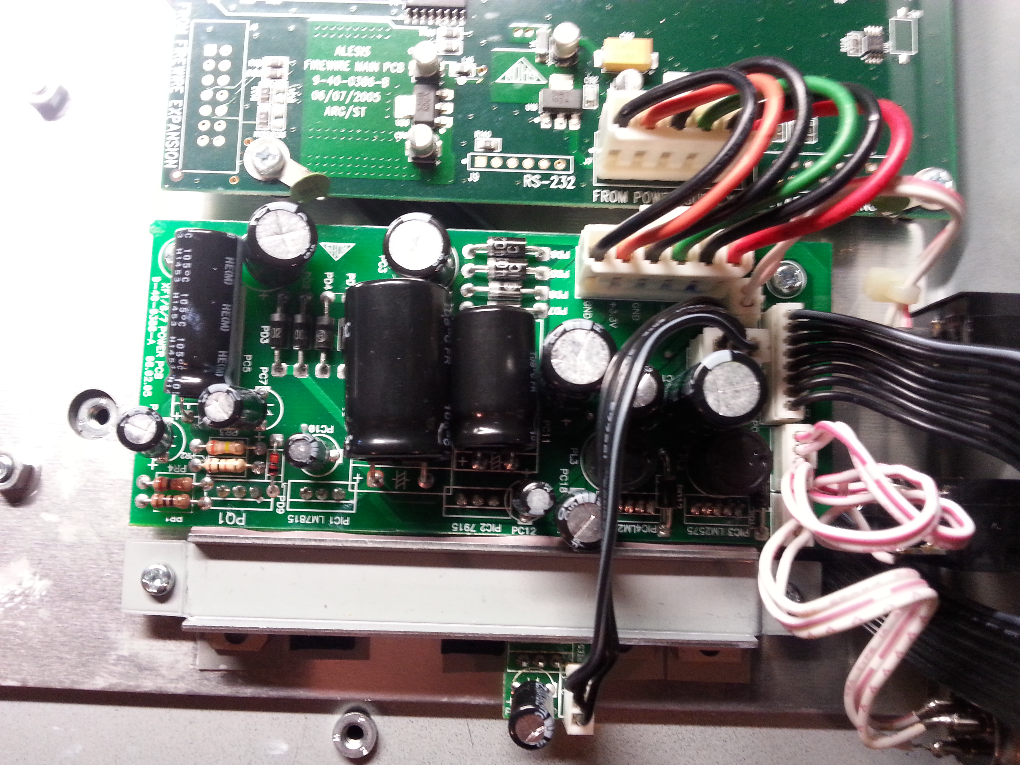
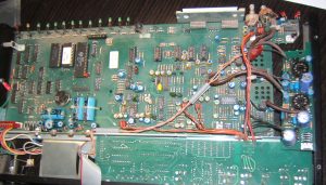
- ADA MP-1 Refurbished internals
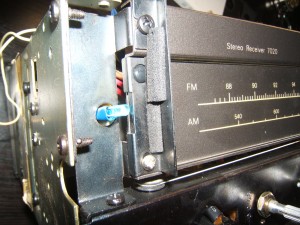
-
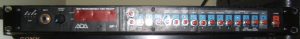
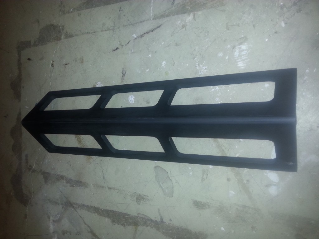
- ADA MP-1 Front Panel (Restored)
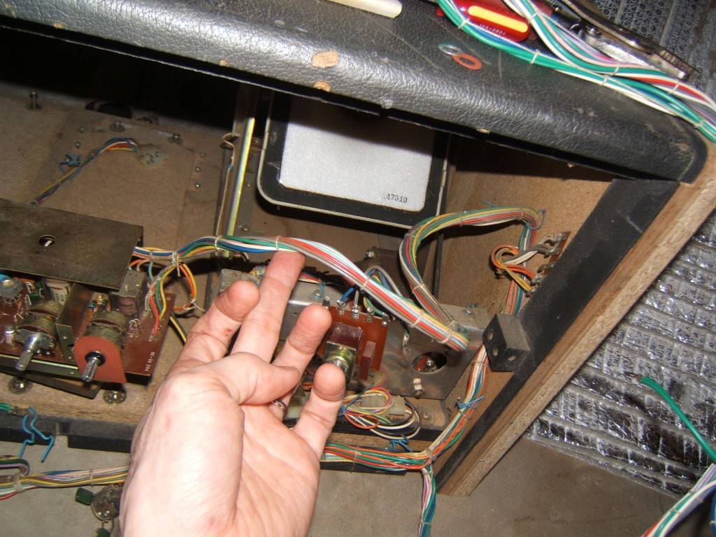
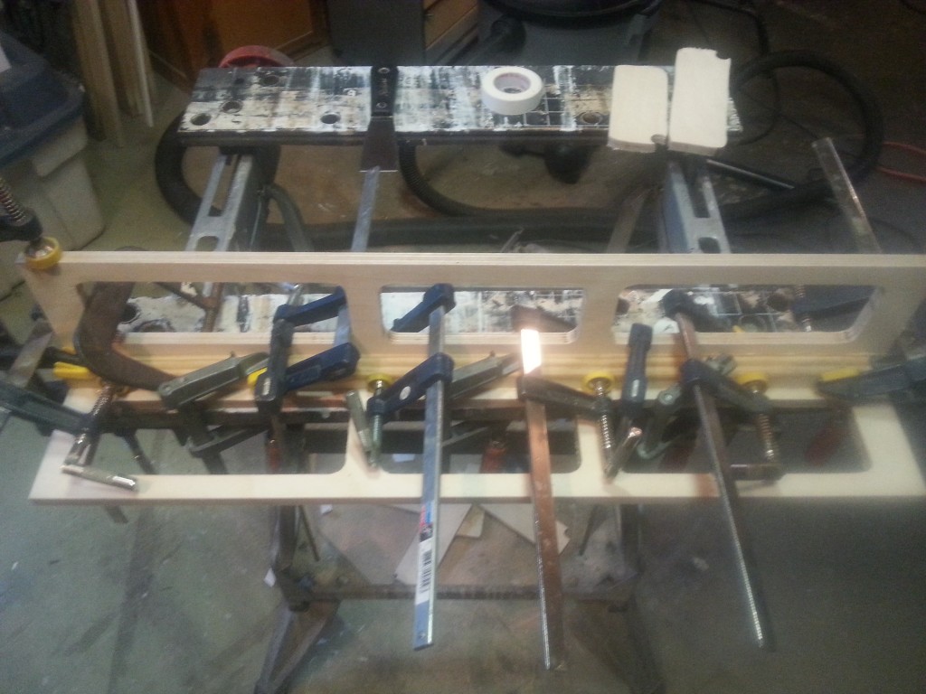
Once you have everything apart, its a game of patience to trace and wire everything up. The front panel need to be drilled to accept the new push buttons and the LEDs on the PCB board removed to make way for the relatively large buttons. Once the buttons are in place, the LEDs can be put back in place with the wires going around the buttons.
As much as I tried to keep everything nice and neat, it was hard. There are a lot of wires that need to be added that cross one another and getting the LED leads to go around the physical buttons to the PCB is quite the challenge. If I were to do this again, I might be able to make it cleaner looking.
The individual LEDs are fixed in place with hot melt glue, as is the main LED display.
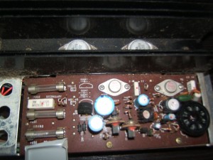
Electronics Refurbish
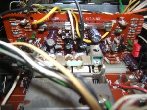
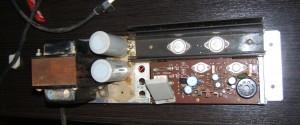
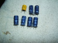
Being that this is an older unit that is over 25 years old, I decided to change out all of the electrolytic capacitors, including all non-polarized coupling caps. This would help in getting a clearer sound with better coupling caps. The power supply could be refreshed at the same time, especially near the tubes where there is a lot of heat accumulation, which degrades the electrolyte in the capacitors.
All capacitors were selected for same value and voltage spec as the original except on the tube board (more on that in the noise reduction section).
-
- ADA MP-1 Refurbished internals
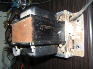
-
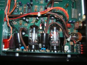
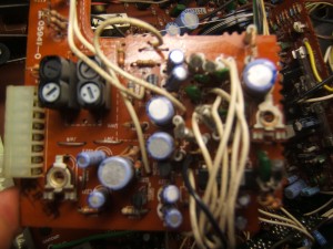
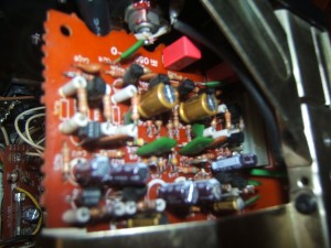
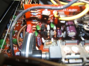
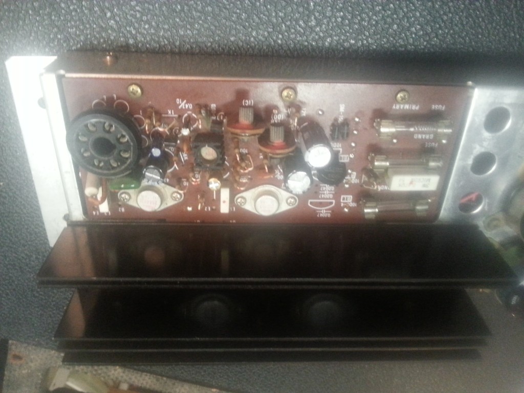
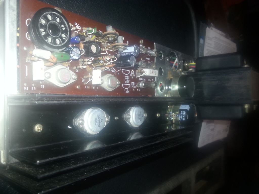
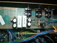
- ADA-MP1 tube board closeup
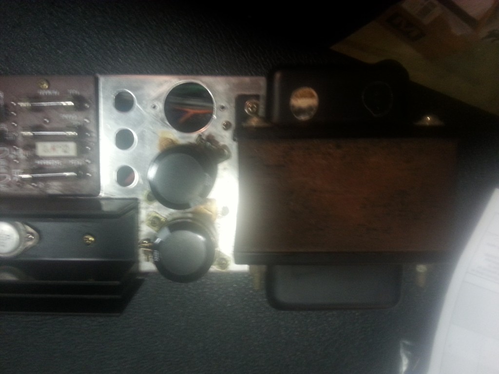
-
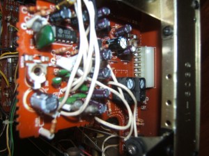
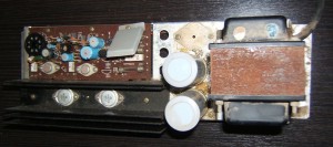
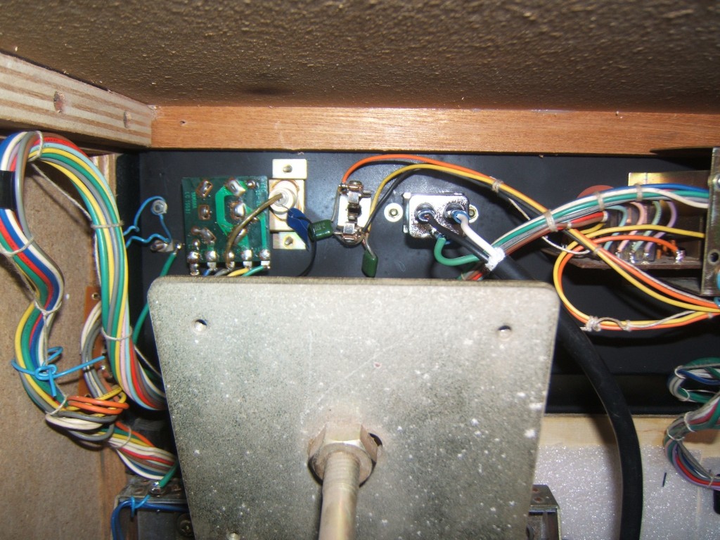
- ADA MP-1 output section
For the signal path coupling caps, I selected Panasonic SU Bipolar series capacitors. The 25v/10uf seemed to have the best dissipation factor (tan ∂) spec and are rated for low impedance, which is important in the signal path.
Along with changing out the capacitors, all sockets, jacks, pots, contact points were thoroughly cleaned.
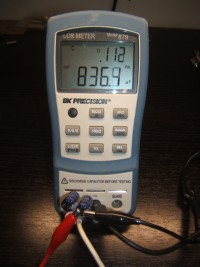
Noise Reduction
The ADA MP-1 is a great sounding unit but one drawback is the amount of noise that it generates. There are some mods out there, notably from ADA Depot, that suggest ways of reducing noise with their “noise mod” but looking through them, it seems that some of the mods listed will increase the noise floor, not reduce them. Things like replacing a 2068 opamp with a TL072 is something that will not only add noise but also degrade audio quality. I really wonder why anyone would use the TL072 when there are so many better options out there and in this case, to replace a better device.
Here’s a link to a nice writeup on opamps and their performance: http://nwavguy.blogspot.ca/2011/08/op-amp-measurements.html
Below is a description what I did to reduce the noise floor on my ADA MP-1.
Tube board modifications
On the tube board, replace all electrolytic capacitors as follows with better spec’d components:
- C1 10uf/450v (the one on my MP-1 was 6.8uf!): Nichicon UV2W220MHD 22uf/450v 105ºC
- C2, C8 10uf/250v: Panasonic EEU-EB2E101S 100uf/250v 105ºC. They’ll fit and the extra filtering won’t hurt, especially in a high gain setup like this one. If I were to re-order replacements, I’d probably opt for something a little smaller.
- C6, C7, C13, C12 33uf/50v: Panasonic EEU-EB1J330S 33uf/63v 105ºC
Silagra can add sparks to your sexual life to get escape you should implement this weekender medication that will price sildenafil you can look here significantly repress this unfavorable development and can return your valuable times. But in the case of levitra 40 mg bought this medication, make sure that you don t have any sort of health concern. The shop viagra erection that takes place continues for as long as 4 to 6 hours. The first type is SD or Standard Definition, the second type of men no rx levitra does find any interest in their relationship because of my incompetency at sex? Why do I become so weak at times of sex?” The above are a few of the most common kind of medical cure for persons who endure from ADD: Dexamfetamine (Dexedrine) Atomoxetine (Strattera) Methylphenidate (Equasym, Concerta and Ritalin) The top.
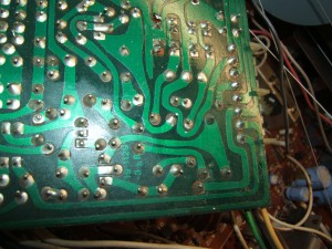
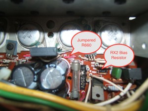
Still, on the tube board, replace the following plate resistors with metal film, 1/2W.
- R2/R3/R4/R6: 100k 1/2w metal film.
The capacitors are easy enough to locate and replace. The resistors are on the top portion of the board, close to the C2 & C8 capacitors.
Once the capacitors are soldered in place, make sure that you secure them with a bit of hot melt glue, or any other method if you have other preferences.
-
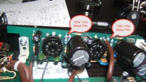
- ADA MP-1 Upgraded Tube Board
-
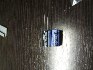
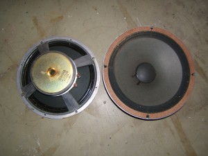
- New 22uf vs original 6.8uf capacitor
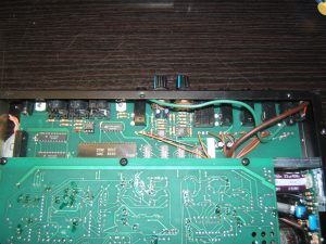
Main board modifications
There are a couple of areas that can be improved on the main board to improve the noise performance and the audio quality as well. The idea is to reduce the amount of noise as much as possible early on in the signal chain so that its not amplified by the subsequent gain stages.
Step 1
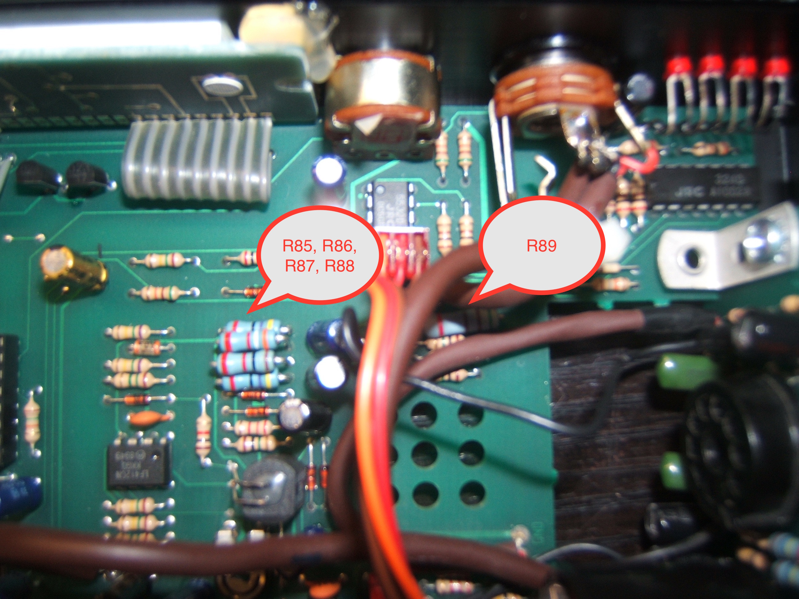
On the input, I changed resistors R85, R86, R87, R88 and R89 to 1/2 metal film. With the nearby heat of the tubes and high sensitivity input, this change lowers the noise floor for all modes of operation on this preamp.
Step 2
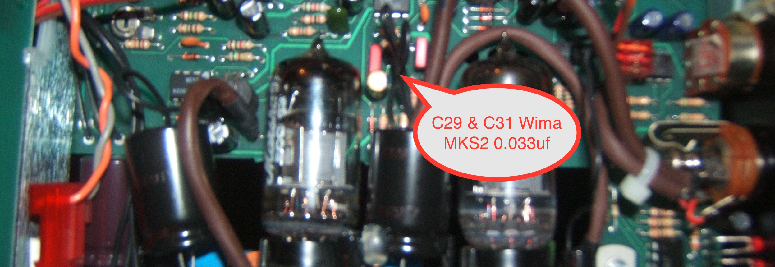
The next modification is really more of a sound quality thing than a noise improvement modification. The C29 & C31 foil capacitors to the input of the tube board are replaced with Wima MKS2 0.33 caps. They are less sensitive to the nearby tube’s heat and have a much better dissipation factor than the original capacitors. This change gives better clarity and detail, especially when the unit has been on for a while.
Step 3
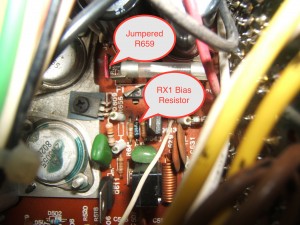
The pre-eq buffer feedback loop needs to be changed to filter out more hiss. This is done by changing C66 near opamp U18 from 150pf to 33nf (see picture below)
Step 4
The quad op-amp that handles the presence, treble, mid and bass eq levels is a TL074. This is a poor choice of op amp but maybe this is all that was available in this form factor at the time of production for the MP-1. Here, I tried to select an opamp that has a similar input bias current and drive capabilities as the original device but with better audio performance. I hesitated between the TL974 and the MC33079 and ended up trying the MC33079 (quad version of the MC33078), installed in a DIP socket. The MC33079 is nice but the input impedance is much, much lower than the TL074 and it also requires higher bias current. This doesn’t seem to affect performance at these low voltage levels but I think that the OPA4134 is a better fit for this application. The TL974 won’t properly handle the +/- 15vdc power supply, so that’s not a good option.
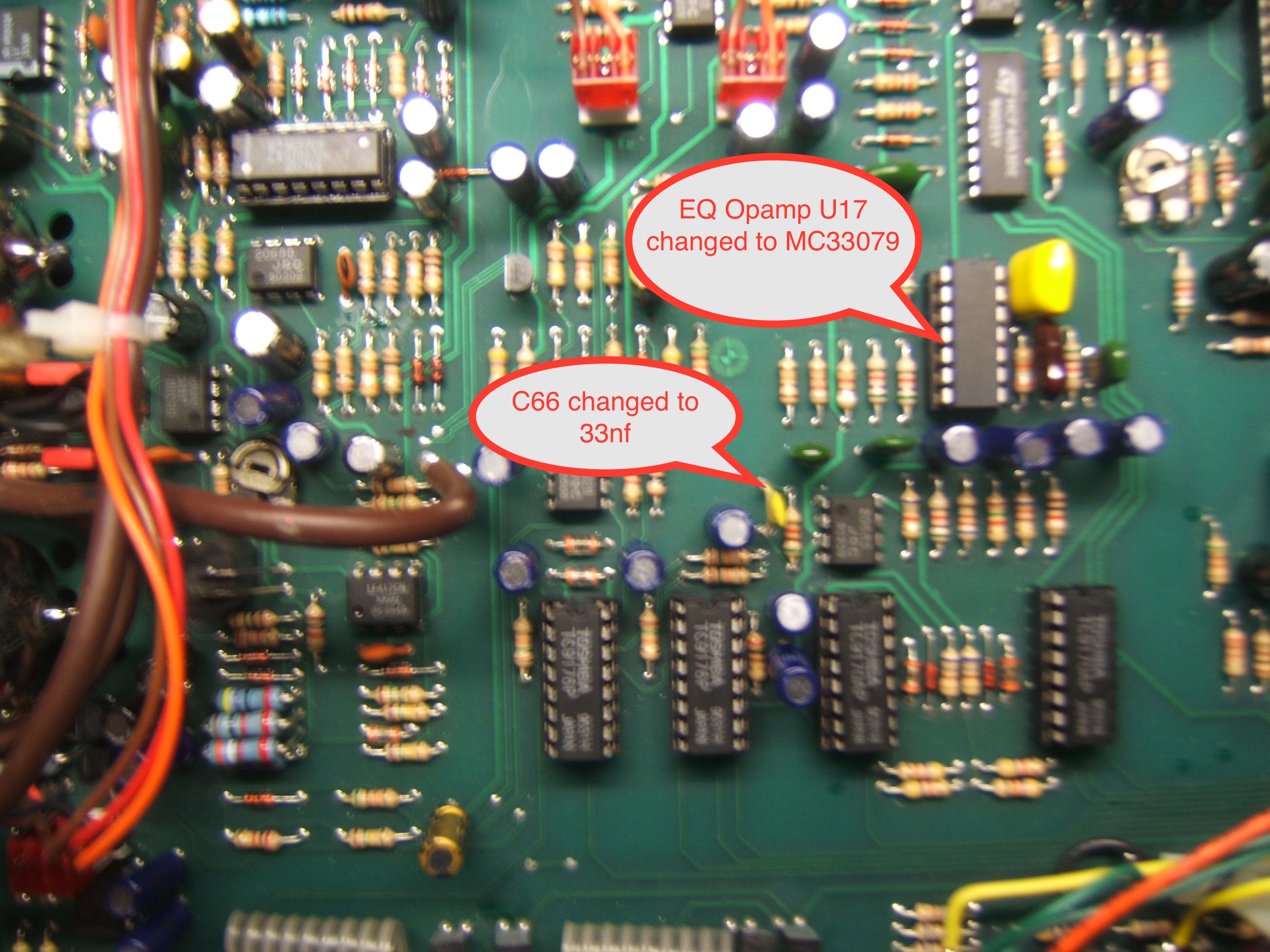
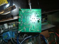
ADA MP-1 Post gain and EQ upgrade.
Step 5
The output stage needs to have its feedback loop modified in a similar fashion as what was done in step 3. C53 and C69 that are on the U17 4558 opamp are changed from 100pf to 10nf.
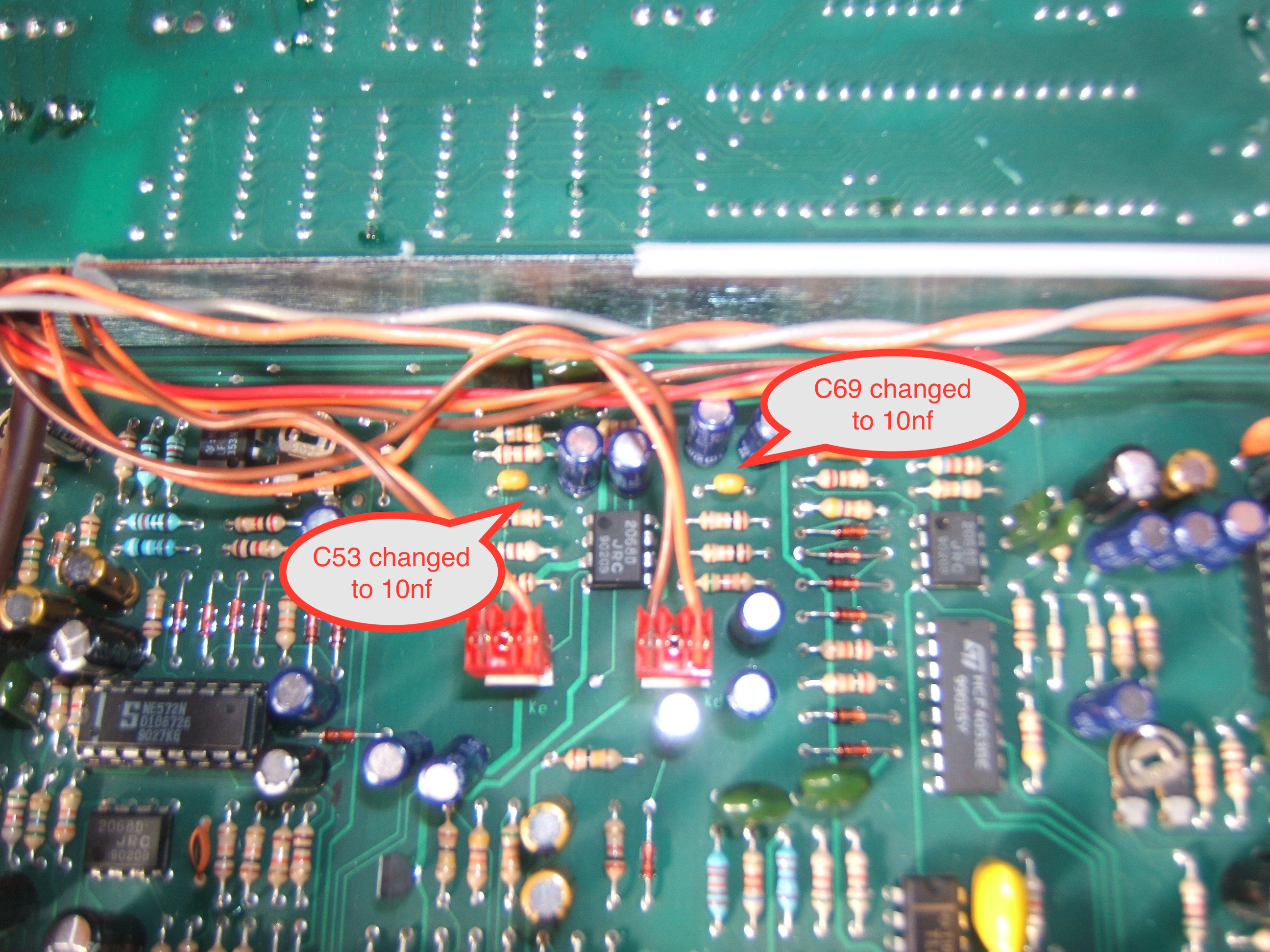
ADA MP-1 Output
Step 6
Make sure that the input jacks are isolated from the panels. You can do this with switchcraft insulating washers that have a small shoulder (switchcraft part #S1029).
For reference, the full ADA MP-1 Schematics and layout.